Here’s what I did to create a battlemap for Arise in Blender.
Blender is a free, open source 3D application. It does 3D modeling, texture painting, compositing, and even video editing. It can be downloaded for free at blender.org.
Once you’ve installed Blender, open the program.
You can use a to select all objects, then x to delete everything and start fresh.
If you’re new to Blender, click Edit > Preferences, then Add-ons. Search for “Node Wrangler”. Click the checkbox to enable this add-on. Hit the hamburger menu in the bottom left of the “Blender Preferences” window and hit “Save Preferences”. Then close the Preferences window.
The Grid
To get started with a map, add a Grid mesh to the world. Hit Shift-a and select Mesh, then Grid.
Once you’ve created the Grid, hit F9 to edit its properties. Set the number of subdivisions to 8 (or 12 for a larger map). This is the number of faces the Grid is divided into. For size, enter 16m for an 8x8 grid with 2 meter squares, or 24m for a 12x12 grid.
To start modeling your map, click on the Grid with the mouse, then hit Tab to enter Edit mode.
Edit mode lets you make changes to the individual vertices, edges, and faces that make up a 3D object. You’ll mostly be working with faces - the squares - but sometimes you’ll be working with edges - the lines between squares - when making ramps and slopes.
In Edit mode, the 1, 2 and 3 keys let you choose whether you’re selecting vertices, edges, or faces. To select faces, for example, hit 3, then click on faces with your mouse.
You can leave Edit mode by hitting Tab again.
Elevating individual squares
In Edit mode, selecting one or more faces and typing e1 will extrude (“e”) a face up by 1 meter (“1”).
The Grid’s normals - where a face is naturally “pointed” at - are aimed straight up. Thus, when you extrude, you’re creating more geometry aimed straight up.
You can extrude multiple times to raise a given square or set of squares.
Ramps and slopes
You can create ramps and slopes by selecting an edge and typing gz-1 (to move down 1 meter), for example. This means move (“g”) along the Z axis (“z”) by negative one meters (“-1”).
The downside is that this will drag neighboring squares’ vertices, which may not be what you want.
An alternative is to extrude the faces around where you intend to put a ramp, then extrude the ramp face separately, then manipulate its edges.
Textures
I experimented with models and textures from the following sources:
- Tiny Texture Pack 1-3 from Screaming Brain Studios
- Pixel Art textures from FlakDeau
- Kenney’s 3D models at kenney.nl
Before adding any other textures or graphics, you should set up a default material for the map. I use a solid black to hide the wireframe I’ll add later, and to match FFT’s black color on the outer borders of its maps.
- Click on the Grid to select it, then go to the Material Properties
- Click the “+” sign to create a new Material slot
- Click “New” to add a new material in that slot
- You’ll see “Surface: Principled BSDF”, “Base Color”, and other properties of your new material
- Click on the color portion of “Base Color” and change it to black, either by dragging the brightness slider down or entering “000000” in the Hex value
If you preview your Grid, you’ll see it’s now all black. This is good, that’s what you want!
Next, let’s add a texture from a file, like one of the Tiny Texture Pack’s images.
- click the “+” sign to add another material. Click “New”
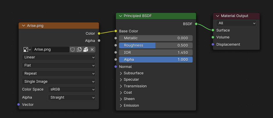
- Under the material properties, click the yellow dot next to “Base Color”
- This should open a menu of color sources to choose from; under “Texture”, pick “Image Texture”
- Click “Open” and select your texture file
With this material selected, go into Edit mode by hitting Tab. You can select individual faces, then click Assign under the Material to change those faces to use this new material.
Repeat with all the materials you want to use.
Textures and tiling
Sometimes you want a texture to apply across the map as a whole, while other times you want it to be tiled or repeated across squares.
To have it repeat, click on the “Shading” view at the top of Blender. This will take you into the Shading editor.
Select the slot that has your chosen material. You should see a node with your chosen image.
Click on the left-most node, representing your image texture. Then hit Control-t. This is a Node Wrangler keyboard shortcut, which should create two nodes to the left: a Texture Coordinates node and a Mapping node.
Under the Mapping node’s Scale properties, set X and Y from 1.0 to 16.0. If your material has been applied to at least one face, you should see the difference immediately. Adjust your rotation and scale values to give the effect you want.
Lighting
You need at least one light for your scene to be visible when it’s rendered.
Click Shift-a, choose Light, then Sun.
Under the Sun’s Item properties, set the Z to 10m and leave other values at zero.
Under the Sun’s “Data” properties on the right, change the Strength to about 5.0.
This should give you a moderately well-lit scene.
If you want to present the scene as being in the morning or evening, use gy to move your Sun along the Y axis, or gx to move along the X axis. Use rx or ry to rotate it along the appropriate axis, to represent a sun shining from a different angle.
You can add other types of lighting to your scene, such as a point light to represent lamps.
You can also add objects with an Emission texture that emit their own light, such as a campfire or magical circle.
Delineating squares
To include lines showing the boundaries of each square:
- Select your grid object, and under the “Modifiers” properties, add a “Wireframe” modifier
- Change the Thickness to 0.02m
- Uncheck the “Replace Original” option
- In Render Properties, turn on “Freestyle”
- In View Layer, turn on “Freestyle”
Choosing a Perspective
Create at least one Camera object. Hit Shift-a and select Camera.
In the Properties panel, look for the Camera properties. Inside, set the Lens Type to “Orthographic”. This gives a “flat” effect that’s important for use as a 2D battlemap.
Next, decide whether you want to export an isometric image, or a top-down image.
Isometric (3D) view
In the Item properties for the camera, set the camera Rotation to X = 54.7 degrees, Y = 0.000004 degrees, Z = 45 degrees. Set the Location to about X = 24m, Y = -24m, Z = 26m.
In the Data properties for the camera object, set “Orthographic Scale” to 30 for an isometric view. This controls the “zoom” on the map.
Top-down (2D) view
In the Item properties for the camera, set the camera Rotation to Z = 90 degrees, and the Location to about Z = 45m, with other Location and Rotation values set to zero.
For Roll20, in the Output properties, set the camera resolution X and Y to 560px. In the Data properties for the camera object, set “Orthographic Scale” to 16. This will exactly match Roll20’s default square grid of 70 pixels per square.
Rendering
Finally, hit F12 to render the image, and click the Image > Save As menu to save your map file!